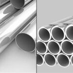
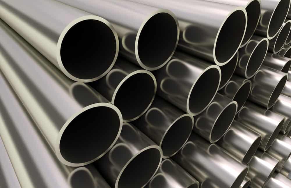
What is Schedule 40 Steel Pipe?
Steel pipe with a schedule of 40 is the most common type of pipe schedule. It is commonly used in water and gas lines, and although galvanization is optional, it is possible to do so. When there is a requirement for ornamentation or support, it may also make an appearance.
Because of its adaptability and performance-enhancing properties, it makes an excellent pipe. Now that it is under so much pressure to perform, let’s talk about what schedule 40 steel pipe is and why it can be the best option for a lot of different tasks.
What Is a Pipe Schedule and How Does It Work?
Pipe schedule, often known as SCH, is a measurement used to determine the nominal wall thickness of a steel pipe.
Metal fabricators used to work with three different pipe sizes in the past: regular, extra strong, and double extra strong. Having these three dimensions without any definition, however, was not sufficient. Steel pipes are now available in a total of 14 different schedules, but the Schedule 40 pipe is the one that sees the most use.
What does the term “schedule 40 pipes” mean?
The numbers that are written on the pipes do not represent any dimensions. To put it another way, a pipe diameter of 40 millimeters or 40 inches is not implied by the designation SCH 40.
The dimensions of steel pipes, both seamless and welded, are governed by the ASME B36.10M standard, which is responsible for determining the parameters of each schedule. The numerical designations for each size are determined by the ASME B36.10M standard.
Grades of Schedule 40 Steel Pipe
The mild steel variety accounts for the vast majority of the scheduled 40 steel pipe inventory. This indicates that its level of carbon is between 0.2 and 0.25 percent of its total mass. This is extremely low, which leads to an alloy that is predominately composed of ferrous SCH. Galvanizing enhances the resistance of steel pipe, size 40, to corrosion. The application of a zinc layer to steel is the process known as galvanizing. In the event that this choice cannot be made, stainless steel pipe in the schedule 40 dimension is also available.
There are a variety of grades available, despite the fact that an A53 steel pipe is most frequently linked with an SCH 40 steel pipe.
Schedule 40 Steel Pipe Dimensions
The thickness of a wall can be calculated using the wall’s exterior diameter as well as its thickness. The wall thickness of a 1/8-inch nominal size schedule 40 pipe is 0.068 inches, while the outer diameter of the pipe measures 0.405 inches. The weight is 0.245 pounds for every square foot that is covered.
A pipe that is used more frequently is the steel pipe with a schedule 40 diameter of four inches. This particular pipe has a wall thickness of 0.237 inches, an outside diameter of 4.5 inches, and a weight per foot of 10.79 pounds.
The Weight of Schedule 40 Steel Pipe
The Weight of Schedule 40 Steel Pipe
What is the maximum weight that a schedule 40 steel pipe can support?
The amount of weight it can support is influenced by a variety of factors. A common black steel pipe made of A53 grade has a yield strength of 30,000 pounds per square inch.
Consider a four-foot span and one-inch pipe. With a quarter-inch permanent deflection, the center should be able to support 300 pounds. If you put another 50 pounds to that pipe, it will collapse on you.
The dimensions, wall thickness, and weight of the Schedule 40 Pipe are listed below.
| Nominal sizes | Outside diameter | Pipe wall thickness | Weight Chart | |||
| inches | OD in inches | OD in mm | inches | mm | lb/ft | kg/m |
| 1/8 | 0.405 | 10.3 | 0.068 | 1.73 | 0.24 | 0.37 |
| 1/4 | 0.540 | 13.7 | 0.088 | 2.24 | 0.42 | 0.84 |
| 1/2 | 0.840 | 21.3 | 0.109 | 2.77 | 0.85 | 1.27 |
| 3/4 | 1.050 | 26.7 | 0.113 | 2.87 | 1.13 | 1.69 |
| 1 | 1.315 | 33.4 | 0.133 | 3.38 | 1.68 | 2.50 |
| 1 1/4 | 1.660 | 42.2 | 0.140 | 3.56 | 2.27 | 3.39 |
| 1 1/2 | 1.900 | 48.3 | 0.145 | 3.68 | 2.72 | 4.05 |
| 2 | 2.375 | 60.3 | 0.154 | 3.91 | 3.65 | 5.44 |
| 2 1/2 | 2.875 | 73.0 | 0.203 | 5.16 | 5.79 | 8.63 |
| 3 | 3.500 | 88.9 | 0.216 | 5.49 | 7.58 | 11.29 |
| 3 1/2 | 4.000 | 101.6 | 0.226 | 5.74 | 9.11 | 13.57 |
| 4 | 4.500 | 114.3 | 0.237 | 6.02 | 10.79 | 16.07 |
| 5 | 5.563 | 141.3 | 0.258 | 6.55 | 14.62 | 21.77 |
| 6 | 6.625 | 168.3 | 0.280 | 7.11 | 18.97 | 28.26 |
| 8 | 8.625 | 219.1 | 0.322 | 8.18 | 28.55 | 42.55 |
| 10 | 10.750 | 273.0 | 0.365 | 9.27 | 40.48 | 60.31 |
| 12 | 12.750 | 323.8 | 0.406 | 10.31 | 53.52 | 79.73 |
| 14 | 14 | 355.6 | 0.375 | 11.13 | 54.57 | 94.55 |
| 16 | 16 | 406.4 | 0.500 | 12.70 | 82.77 | 123.30 |
| 18 | 18 | 457.0 | 0.562 | 14.27 | 104.67 | 155.80 |
| 20 | 20 | 508.0 | 0.594 | 15.09 | 123.11 | 183.42 |
| 24 | 24 | 610.0 | 0.688 | 17.48 | 171.29 | 255.41 |
| 32 | 32 | 813.0 | 0.688 | 17.48 | 230.08 | 342.91 |
| Metric diameter | Inch | Out diameter | Out diameter points to the thickness | ||
| A | B | ASME | STD | SCH40 | SCH80 |
| 8 | 1/4′ | – | – | – | – |
| 10 | 3/8 | – | – | – | – |
| 15 | 1/2″ | 21.3 | 2.77 | 2.77 | 3.73 |
| 20 | 3/4″ | 26.7 | 2.87 | 2.87 | 3.91 |
| 25 | 1″ | 33.4 | 3.38 | 3.38 | 4.55 |
| 32 | 1.1/4″ | 42.2 | 3.56 | 3.56 | 4.85 |
| 40 | 1.1/2″ | 48.3 | 3.68 | 3.68 | 5.08 |
| 50 | 2″ | 60.3 | 3.91 | 3.91 | 5.54 |
| 65 | 2.1/2″ | 73 | 5.16 | 5.16 | 7.01 |
| 80 | 3″ | 88.9 | 5.49 | 5.49 | 7.62 |
| 90 | 3.1/2″ | 101.6 | 5.74 | 5.74 | 8.08 |
| 100 | 4″ | 114.3 | 6.02 | 6.02 | 8.56 |
| 125 | 5″ | 141.3 | 6.55 | 6.55 | 9.53 |
| 150 | 6″ | 168.3 | 7.11 | 7.11 | 10.97 |
| 200 | 8″ | 219.1 | 8.18 | 8.18 | 12.7 |
| 250 | 10″ | 273 | 9.27 | 9.27 | 15.09 |
| 300 | 12″ | 323.8 | 9.53 | 10.31 | 17.48 |
| 350 | 14″ | 355.5 | 9.53 | 11.13 | 19.05 |
| 400 | 16″ | 406.4 | 9.53 | 12.7 | 21.44 |
| 450 | 18″ | 457.2 | 9.53 | 14.27 | 23.83 |
| 500 | 20″ | 508 | 9.53 | 15.09 | 26.19 |
| 550 | 22″ | 558.8 | 9.53 | – | 28.58 |
| 600 | 24″ | 609.6 | 9.53 | 17.48 | 30.96 |
| 650 | 26″ | 660.4 | 9.53 | – | – |
| 700 | 28″ | 711.2 | 9.53 | – | – |
| 750 | 30″ | 762 | 9.53 | – | – |
| 800 | 32″ | 812.8 | 9.53 | 17.48 | – |
| 850 | 34″ | 863.5 | 9.53 | 17.48 | – |
| 900 | 36″ | 914.4 | 9.53 | 19.05 | – |
| 950 | 38″ | 965.2 | 9.53 | – | – |
| 1000 | 40″ | 1016 | 9.53 | – | – |
| 1050 | 42″ | 1066.8 | 9.53 | – | – |
| 1100 | 44″ | 1117.6 | 9.53 | – | – |
| 1150 | 46″ | 1168.4 | 9.53 | – | – |
| 1200 | 48″ | 1219.2 | 9.53 | – | – |
What does NPS (Nominal Pipe Size) stand for?
The interior diameter (ID) but not the outer diameter (OD) of a pipe is represented by the NPS size. If the schedule number on a set size is changed, the inside diameter (ID) but not the outside diameter (OD) is impacted (OD). The American Standard Association created Nominal Pipe Sizing to replace the previously used Iron Pipe Sizing. This North American standard is used for high or low pressure and temperature pipes.
| NPS | OD | SCH | Wall Thickness | ID |
| 1.000” | 1.315” | SCH 40 | 0.133” | 1.049” (approx.) |
| 1.000” | 1.315” | SCH 80 | 0.179” | 0.957” (approx.) |
All pipes are identified by their NPS and Sch numbers. The schedule number is used to estimate the internal diameter.
Schedule 40 Carbon Steel Pipe Pressure Rating
Steel piping diameter od chart, wall thickness, and weight per foot are all freely available.
25.4 mm = 1 in (inch)
6.89510-2 bar = 1 psi (lb/in2) = 6,894.8 Pa (N/m2)
| Maximum Allowable Pressure (psi) (kPa) | ||
| NPS | Outside Diameter (OD) | Schedule |
| (in) | (in)
(mm) |
40 |
| 1/4 | 0.54
13.7 |
7985
55057 |
| 3/8 | 0.675
17.1 |
6606
45548 |
| 1/2 | 0.84
21.3 |
6358
43838 |
| 3/4 | 1.05
26.7 |
5273
36357 |
| 1 | 1.315
33.4 |
4956
34172 |
| 1 1/4 | 1.66
42.2 |
4133
28497 |
| 1 1/2 | 1.9
48.3 |
3739
25780 |
| 2 | 2.375
60.3 |
3177
21905 |
| 2 1/2 | 2.875
73 |
3460
23857 |
| 3 | 3.5
88.9 |
3024
20850 |
| 3 1/2 | 4
102 |
2769
19092 |
| 4 | 4.5
114 |
2581
17796 |
| 5 | 5.563
141 |
2273
15672 |
| 6 | 6.625
168 |
2071
14280 |
| 8 | 8.625
219 |
1829
12611 |
| 10 | 10.75
273 |
1664
11473 |
| 12 | 12.75
324 |
1560
10756 |
| 14 | 14
356 |
1533
10570 |
| 16 | 16
406 |
1531
10556 |
| 18 | 18
457 |
1530
10549 |
| 20 | 20
508 |
1455
10032 |
| 22 | 22
559 |
|
| 24 | 24
610 |
1405
9687 |
| 30 | 30
762 |
|
| 32 | 32
813 |
1054
7267 |
| 34 | 34
864 |
992
6840 |
| 36 | 36
914 |
1021
7040 |
| 42 | 42
1067 |
875
6033 |
Pipe Dimensions and Wall Thickness for Schedule 40
| Pipe
Sizes* |
O.D.
(in.) |
Schedule (40) Pipe
Wall Thickness (in.)** |
|
| Sch.40 | |||
| Wall (in) | I.D. (in) | ||
| 1/8″ | 0.41 od | 0.07 in | 0.269 id |
| Weight
(lbs/ft.) |
Steel | 0.247 lbs/ft | |
| Stainless | |||
| Aluminum | |||
| 1/4″ | 0.54 od | 0.090 in | 0.364 id |
| Weight
(lbs/ft.) |
Steel | 0.429 lbs/ft | |
| Stainless | |||
| Aluminum | 0.147 lbs/ft | ||
| 3/8″ | 0.675 od | 0.091 in | 0.493 id |
| Weight
(lbs/ft.) |
Steel | 0.570 lbs/ft | |
| Stainless | |||
| Aluminum | 0.196 lbs/ft | ||
| 1/2″ | 0.840 od | 0.109 in | 0.622 id |
| Weight
(lbs/ft.) |
Steel | 0.850 lbs/ft | |
| Stainless | |||
| Aluminum | 0.294 lbs/ft | ||
| 3/4″ | 1.050 od | 0.113 in | 0.824 id |
| Weight
(lbs/ft.) |
Steel | 1.13 lbs/ft | |
| Stainless | |||
| Aluminum | 0.391 | ||
| 1″ | 1.315 od | 0.133 in | 1.049 id |
| Weight
(lbs/ft.) |
Steel | 1.68 lbs/ft | |
| Stainless | |||
| Aluminum | 0.581 lbs/ft | ||
| 1-1/4″ | 1.66 od | 0.140 in | 1.380 id |
| Weight
(lbs/ft.) |
Steel | 2.27 lbs/ft | |
| Stainless | |||
| Aluminum | 0.785 lbs/ft | ||
| 1-1/2″ | 1.90 od | 0.145 in | 1.610 id |
| Weight
(lbs/ft.) |
Steel | 2.72 lbs/ft | |
| Stainless | |||
| Aluminum | 0.939 lbs/ft | ||
| 2″ | 2.375 od | 0.154 in | 2.067 id |
| Weight
(lbs/ft.) |
Steel | 3.66 lbs/ft | |
| Stainless | |||
| Aluminum | 1.260 lbs/ft | ||
| 2-1/2″ | 2.875 od | 0.203 in | 2.469 id |
| Weight
(lbs/ft.) |
Steel | 5.80 lbs/ft | |
| Stainless | |||
| Aluminum | 2.000 lbs/ft | ||
| 3″ | 3.50 od | 0.216 in | 3.068 id |
| Weight
(lbs/ft.) |
Steel | 7.58 lbs/ft | |
| Stainless | |||
| Aluminum | 2.620 lbs/ft | ||
| 3-1/2″ | 4.00 od | 0.226 in | 3.550 id |
| Weight
(lbs/ft.) |
Steel | 9.12 lbs/ft | |
| Stainless | |||
| Aluminum | 3.150 lbs/ft | ||
| 4″ | 4.50 od | 0.237 in | 4.026 id |
| Weight
(lbs/ft.) |
Steel | 10.80 lbs/ft | |
| Stainless | |||
| Aluminum | 3.730 lbs/ft | ||
| 5″ | 5.563 od | 0.258 in | 5.047 id |
| Weight
(lbs/ft.) |
Steel | 14.63 lbs/ft | |
| Stainless | |||
| Aluminum | 5.050 lbs/ft | ||
| 6″ | 6.625 od | 0.280 in | 6.065 id |
| Weight
(lbs/ft.) |
Steel | 18.99 lbs/ft | |
| Stainless | |||
| Aluminum | 6.560 lbs/ft | ||
| 8″ | 8.625 od | 0.322 in | 7.981 id |
| Weight
(lbs/ft.) |
Steel | 28.58 lbs/ft | |
| Stainless | |||
| Aluminum | 9.88 lbs/ft | ||
*Nominal sizes apply; Pipe Size is a generic Industry Size Standard that is solely used as a guide. ** Each manufacturer’s tolerances may differ slightly.

Schedule 40 Steel Pipe Nominal Wall Thickness
Pipe Schedule Chart ANSI/ASME B36.10M
Weight Chart for Schedule 40 Carbon Steel Line Pipe
SCH 40 Nominal pipe size (NPS)
| NPS | 1/2 | 3/4 | 1 | 1¼ | 1½ | 2 | 2½ | 3 | 3½ | 4 |
| DN | 15 | 20 | 25 | 32 | 40 | 50 | 65 | 80 | 90 | 100 |
Notes:
The corresponding DN = 25 multiplied by the NPS number for NPS 4.
The wall thickness between SCH 40 and STD differs from NPS 12 onwards, and the wall thickness between schedule 80 and XS differs from NPS 10 onwards.
For NPS 4, the DN = 25 multiplied by the NPS number.
From NPS 12 onwards, the wall thickness between SCH 40 and STD differs, while the wall thickness between schedule 80 and XS differs from NPS 10 onwards.
Buy 2 Inch Schedule 40 galvanized and black steel pipe at price in India
| INCH | NPS | Schedule 40 ASTM A106/ A53/ API 5L Grade B Seamless Pipe Price | |||||||||
| MSL | ISMT | JSL | USL | BAO | Lontrin | SMTM | TENARIS | V&M | Wuxi | ||
| 1/2 | 15 | 1,313.53 | 1,316.18 | 1,330.88 | – | 1,029.41 | 1,036.76 | 1,460.59 | 1,396.06 | 1,425.47 | 1,012.06 |
| 3/4 | 20 | 1,112.94 | 1,095.59 | 1,110.29 | – | 954.88 | 963.24 | 1,250.00 | 1,176.47 | 1,205.88 | 938.53 |
| 1 | 25 | 946.88 | 948.53 | 963.24 | – | 881.35 | 889.71 | 1,102.94 | 1,029.41 | 1,058.82 | 875.00 |
| 1.25 | 32 | 911.76 | 904.41 | 919.12 | – | 851.94 | 860.29 | 1,058.82 | 985.29 | 1,014.71 | 845.59 |
| 1.5 | 40 | 818.82 | 821.47 | 816.18 | – | 807.82 | 816.18 | 955.88 | 882.35 | 911.76 | 821.47 |
| 2 | 50 | 799.12 | 786.76 | 821.47 | – | 622.65 | 625.00 | 948.18 | 869.65 | 899.06 | 612.29 |
| 2.5 | 65 | 799.12 | 786.76 | 821.47 | – | 622.65 | 625.00 | 948.18 | 869.65 | 899.06 | 612.29 |
| 3 | 80 | 799.12 | 786.76 | 821.47 | – | 622.65 | 625.00 | 948.18 | 869.65 | 899.06 | 612.29 |
| 3.5 | 90 | 799.12 | 786.76 | 821.47 | – | 622.65 | 625.00 | 948.18 | 869.65 | 899.06 | 612.29 |
| 4 | 100 | 799.12 | 786.76 | 821.47 | 755.29 | 622.65 | 625.00 | 948.18 | 869.65 | 899.06 | 612.29 |
| 5 | 125 | 799.12 | 786.76 | 821.47 | 755.29 | 622.65 | 625.00 | 948.18 | 869.65 | 899.06 | 612.29 |
| 6 | 150 | 799.12 | 786.76 | 821.47 | 755.29 | 622.65 | 625.00 | 948.18 | 869.65 | 899.06 | 612.29 |
| 8 | 200 | 799.12 | 786.76 | 821.47 | 755.29 | 647.06 | 654.41 | 948.18 | 869.65 | 899.06 | 639.71 |
| 10 | 250 | 799.12 | 786.76 | – | 755.29 | 647.06 | 654.41 | 948.18 | 869.65 | 899.06 | 639.71 |
| 12 | 300 | 862.94 | – | – | 755.29 | 647.06 | 654.41 | 1,000.00 | 926.47 | 955.88 | 639.71 |
| 14 | 350 | 862.94 | – | – | 755.29 | 661.76 | 669.12 | 1,000.00 | 926.47 | 955.88 | 654.41 |
| 16 | 400 | 886.35 | – | – | – | 661.76 | 669.12 | 1,029.41 | 955.88 | 985.29 | 654.41 |
| 18 | 450 | 886.35 | – | – | – | 676.47 | 683.82 | 1,029.41 | 955.88 | 985.29 | 669.12 |
| 20 | 500 | 886.35 | – | – | – | 676.47 | 683.82 | 1,029.41 | 955.88 | 985.29 | 669.12 |
| 22 | 550 | – | – | – | – | 705.88 | 713.24 | 1,176.47 | 1,029.41 | 1,132.35 | 698.53 |
| 24 | 600 | – | – | – | – | 705.88 | 713.24 | 1,176.47 | 1,029.41 | ||
Read More:
ERW VS. SEAMLESS PIPE DIFFERENCE: Electric Resistance Welding (ERW) pipe is made by rolling metal and then welding it longitudinally throughout its length. ERW pipe has a welded junction in its cross-section throughout its length, whereas seamless pipe is created by extruding metal to the required length.
HASTELLOY VS INCONEL: Inconel is an oxidation-corrosion-resistant alloy that works well in high-temperature and high-pressure environments. When Inconel alloy is heated, a thick, stable oxide layer forms on the surface, protecting it from further attack.